edited by
14,714 views
29 votes
29 votes

Consider a combination of $\text{T}$ and $\text{D}$ flip-flops connected as shown below. The output of the $\text{D}$ flip-flop is connected to the input of the $\text{T}$ flip-flop and the output of the $\text{T}$ flip-flop is connected to the input of the $\text{D}$ flip-flop.

Initially, both $Q_{0}$ and $Q_{1}$ are set to $1$ (before the $1^{\text{st}}$ clock cycle). The outputs

  1. $Q_{1}Q_{0}$ after the $3^{\text{rd}}$ cycle are $11$ and after the $4^{\text{th}}$ cycle are $00$ respectively.
  2. $Q_{1}Q_{0}$ after the $3^{\text{rd}}$ cycle are $11$ and after the $4^{\text{th}}$ cycle are $01$ respectively.
  3. $Q_{1}Q_{0}$ after the $3^{\text{rd}}$ cycle are $00$ and after the $4^{\text{th}}$ cycle are $11$ respectively.
  4. $Q_{1}Q_{0}$ after the $3^{\text{rd}}$ cycle are $01$ and after the $4^{\text{th}}$ cycle are $01$ respectively.
edited by

7 Answers

0 votes
0 votes

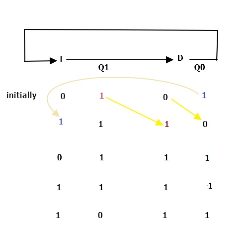
In this question it is clearly told Q1 and Q0 value 1

But nothing told about value of T and D initially

So, we take T and D as 0 and as well as take T and D as 1, and need to check the value

Now to desceribe

firstly, Q0=1 which is connected to FF T and makes Q1=1(because Q0 passes through T=0 and no toggle will be there) But before making Q1as 1,it passes through T FF ,it and makes value of FF T as 1.

In the mean time Q1 previous value which was 1 passes through D FF and makes it 1 and changes Q0 value as 0(as Q0 depends on D FF value , and not the previous input value)

So, 1st clock cycle completed here

In 2nd clock cycle similarly Q0=0 pass through T=1 and makes Q1=1 and T will be 0 now

Now, Q1 which was 1 pass through D FF and go for furthur

For more clearity , check the picture

For  taking T and D as 1 both picture will be like this

So, T and D both 1 will not work in this case

We have to take both FF as 0 initially

Then option B will only give correct value

edited by
0 votes
0 votes

Ans: (B)

The state table can be constructed from given flip flop diagram as:

State Table
D T Q0 Q1 Q0N Q1N
0 0 0 0 0 0
1 0 0 1 1 1
0 1 1 0 0 1
1 1 1 1 1 0

State Transition Diagram is

After 3rd Cycle Q1=1 & Q0=1.

After 4th Cycle Q1=0 & Q0=1.

Therefore, Answer is (B) Option.

0 votes
0 votes

$$\begin{array}{|c|c|c|c|c|c|} \hline  \bf {CP}& \bf{Q_1} & \bf {Q_0}& \bf {Q_1^+=T\oplus Q_1=Q_0\oplus Q_1} &  \bf{Q_0^+=Q_1 }& \bf {CP}\\\hline0&1&1&0&1&1\\ 1&0&1&1&0&2\\2&1&0&\mathbf{1}&\mathbf{1}&3\\ 3&1&1&\mathbf{0}&\mathbf{1}&4 \\\hline\end{array}$$

Correct Answer (B)

Answer:

Related questions

45 votes
45 votes
4 answers
1
39 votes
39 votes
6 answers
2
Arjun asked Feb 14, 2017
13,741 views
When two $8\text{-bit}$ numbers $A_{7}\cdots A_{0}$ and $B_{7}\cdots B_{0}$ in $2$'s complement representation (with $A_{0}$ and $B_{0}$ as the least significant bits) ar...