Step 1)Since it is a 3-bit counter, the number of flip-flops required is three.
Step 2)Let the type of Flip-Flops be RS- Flip Flops
Step 3)Let the three flip-flops be A,B and C.
Step 4)The state table is shown in Table (a)
State Table:-
| Present State |
Next State |
| A B C |
A B C |
| 0 0 0 |
100 |
| 1 0 0 |
010 |
| 0 1 0 |
001 |
| 0 0 1 |
110 |
| 1 1 0 |
000 |
Step 5)The next step is to develop an excitation table from the state table which is shown in Table(b)
| Output State Transitions |
Flip-Flop Inputs |
| Present State Next State |
TA TB TC |
| 000 100 |
1 0 0 |
| 100 010 |
1 1 0 |
| 010 001 |
0 1 1 |
| 001 110 |
1 1 1 |
| 110 000 |
1 1 0 |
Step 6:Now transfer the T states of flip-flop inputs from the excitation table to Karnaugh Maps in Table(i),(ii) and (iii) to derive a simplified Boolean Expression for each Flip-Flop Input.
Table(i) K-Map for TA
| |
B'C'
00
|
B'C
01
|
BC
11 |
BC'
10 |
| A'0 |
0
1 |
1
1 |
3 |
2 |
| A 1 |
4
1 |
5 |
7 |
6
1 |
Table(ii) K-Map for TB
| |
B'C'
00 |
B'C
01
|
BC
11
|
BC'
10
|
| A'0 |
0 |
1 1 |
3 |
2 1 |
| A 1 |
4 1 |
5 |
7 |
6 1 |
Table(iii) for TC
| |
B'C'
00
|
B'C
01
|
BC
11
|
BC'
10
|
| A' 0 |
0 |
1 1 |
3 |
2 1 |
| A 1 |
4 |
5 |
7 |
6 |
From the K-Maps, the following expressions for the T-input of each Flip-Flop are obtained:
TA=A'B'+B'C'+AC'
TB=A'B'C+AC'+BC'
TC=A'B'C+A'BC'
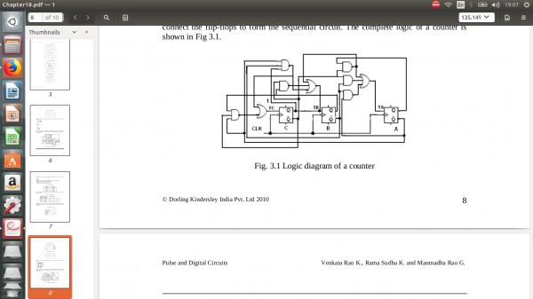
Step 7: The final step is to implement the combinational logic from the equations and connect the flip-flops to form the sequential circuit. The combinational logic of a counter is shown in Fig (c)
Fig(C)Logic Diagram of a Counter