Consider the synchronous sequential circuit in the below figure
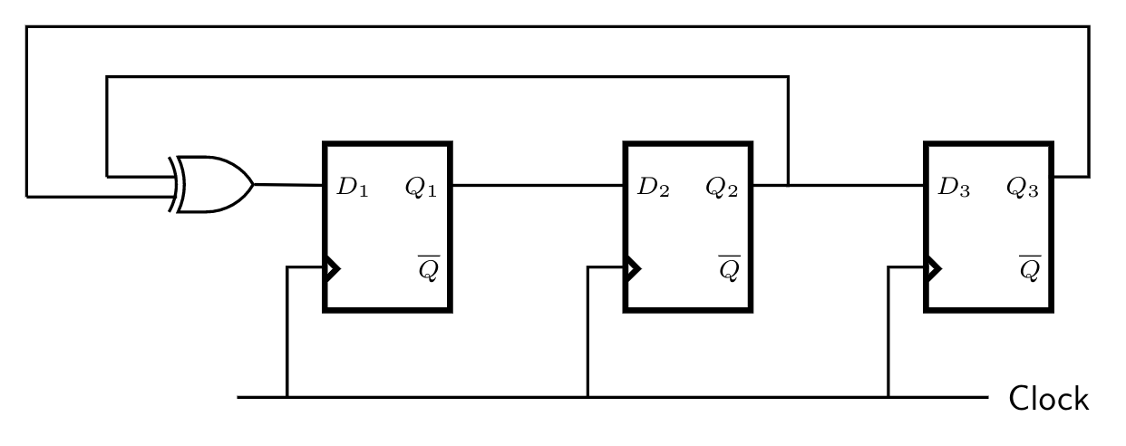
Draw a state diagram, which is implemented by the circuit. Use the following names for the states corresponding to the values of flip-flops as given below.
$$\begin{array}{|l|l|}\hline \textbf{Q1} & \textbf{Q2} & \textbf{Q3} & \textbf{State} \\\hline \text{0} & \text{0} & \text{0} & \text{S$_0$} \\\hline \text{0} & \text{0} & \text{1} & \text{S$_1$} \\\hline – & – & – & – \\\hline – & – & – & – \\\hline – & – & – & – \\\hline \text{1} & \text{1} & \text{1} & \text{S$_7$} \\\hline \end{array}$$