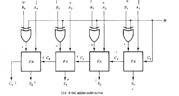
1 votes 1 votes The adder-subtractor circuit of figure has the following values for mode input M and data inputs A and B. In each case, determine the values of the outputs: $S _ 4 S _3 S _2 S _1$ and $C _5$. M A B 0 0111 0110 0 1000 1001 1 0101 1000 1 0000 1010 Digital Logic digital-logic morris-mano combinational-circuit adder digital-circuits + – ajaysoni1924 asked Apr 3, 2019 ajaysoni1924 3.4k views answer comment Share Follow See all 0 reply Please log in or register to add a comment.