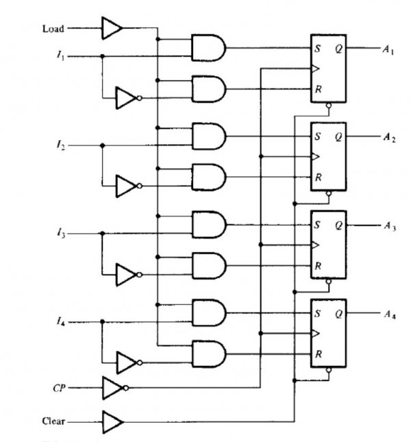
Change the asynchronous-clear-circuit of the figure to the synchronous-clear-circuit, The modified register will have parallel load capability and asynchronous clear capability, but no asynchronous clear circuit. The register is cleared synchronously when the clock pulse in the CP goes through a negative transition provided R = 1 and S = 0 in all the flip-flops.
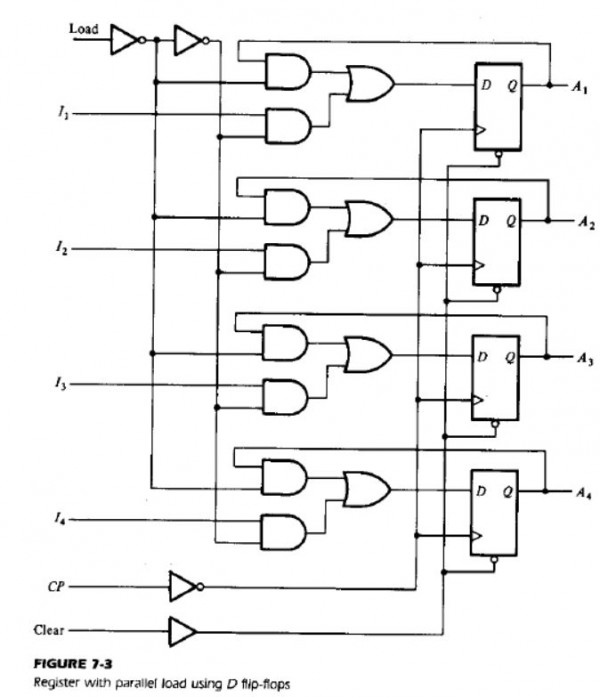
- Repeat the above problem for the figure given below. Here the circuit will be cleared synchronously when the clock input CP goes through a negative transition while the D input of all the flip-flops are 0.