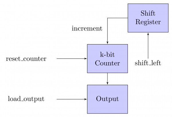
The data path shown in the figure computes the number of $1s$ in the $32-bit$ input word corresponding to an unsigned even integer stored in the shift register.
The unsigned counter, initially zero, is incremented if the most significant bit of the shift register is $1.$
The microprogram for the control is shown in the table below with missing control words for microinstructions $I_1, I_2, \ldots I_n.$
$$\begin{array}{|l|c|c|c|} \hline \textbf {Microinstruction} & \textbf{Reset_Counter}& \textbf{Shift_left} & \textbf{Load_output} \\\hline \text{BEGIN} & \text{1} & \text{0} & \text{0} \\\hline \text{I1}& \text{$?$} & \text{$?$} & \text{$?$} \\\hline \text{:} & \text{:} & \text{:} & \text{:} \\\hline \text{In} & \text{$?$} & \text{$?$} & \text{$?$} \\\hline \text{END} & \text{0} & \text{0} & \text{1} \\\hline \end{array}$$
The counter width (k), the number of missing microinstructions (n), and the control word for microinstructions $I_1, I_2, \ldots I_n$ are, respectively,
- $32, 5, 010$
- $5, 32, 010$
- $5, 31, 011$
- $5, 31, 010$