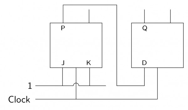
37 votes 37 votes The following arrangement of master-slave flip flops has the initial state of $P, Q$ as $0, 1$ (respectively). After three clock cycles the output state $P, Q$ is (respectively), $1, 0$ $1, 1$ $0, 0$ $0, 1$ Digital Logic gatecse-2000 digital-logic circuit-output normal flip-flop + – Kathleen asked Sep 14, 2014 • edited May 19, 2019 by ajaysoni1924 Kathleen 11.7k views answer comment Share Follow See all 6 Comments See all 6 6 Comments reply Show 3 previous comments Abhishek Gupta 1 commented Jun 29, 2018 reply Follow Share Thanks for replying !! In asynchronous counter the output of 1 FF is given to other FF and I thnkt because of that it's Asynchronous . Pleaee Correct me if I am wrong. 0 votes 0 votes lakshaysaini2013 commented Jun 29, 2018 reply Follow Share Yes, you are right that in asynchronous counter the output of 1FF is given to other FF but the output is given as the Clock of other FF while in the synchronous we have same clock. Please Correct me if I am wrong. 1 votes 1 votes register_user_19 commented Oct 31, 2018 reply Follow Share After three clock cycle output states P,Q is 1,0 (no change in answer) 0 votes 0 votes Please log in or register to add a comment.
0 votes 0 votes $Option A$ Rishi yadav answered Dec 5, 2018 Rishi yadav comment Share Follow See 1 comment See all 1 1 comment reply srestha commented Aug 17, 2019 reply Follow Share Will 1st input of D FF will be $0$ or $1?$ I mean will it take prev input of P or value after generation of P?? How to differentiate this point? 0 votes 0 votes Please log in or register to add a comment.