edited by
678 views

1 Answer

Best answer
3 votes
3 votes

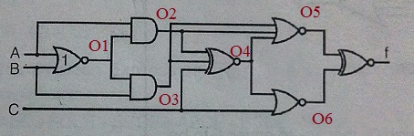
I have marked output from various gates as O1, O2, O3, O4 , O5 and O6

Now f = O5 EXOR O6

O1 = A NOR B = (A+B)' = A'B'

O2 = O1 AND A = (A'B').A = 0

O3 = O1 AND B = (A'B').B = 0

O4 = O2 XNOR O3 XNOR C = 0 XNOR 0 XNOR C = 1 XNOR C = C

O5 = (O2+O3+O4)' = (0+0+C)' = C'

O6 = O4 NOR C = (C+C)' = C'

f = O5 EXOR O6 = C' XNOR C' = C' + C = 1

So Answer can be both B) and D)

selected by

Related questions

2 votes
2 votes
2 answers
1
Sandeep Singh asked Jan 15, 2016
3,224 views
All the logic gates in the circuit shown below have finite propagation delay. The circuit can be used as a clock generator, ifa) X = 0b) X = 1c) X = 0 or 1d) X = Y
0 votes
0 votes
0 answers
2
3 votes
3 votes
1 answer
4
ashish pal asked Dec 28, 2017
8,985 views
A 32 : 1 MUX has to be designed using a 16 : 1 MUX. It was found that for this task we require ‘X ’ number of 16 : 1 MUX and “Y ” number of two input OR gates, th...