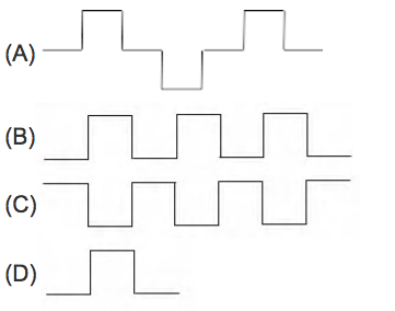
1 votes 1 votes In the circuit shown in figure, value of input P goes from 0 to 1 and that of Q goes from 1 to 0. Which output forms shown in figure represents the output under a static hazard condition? Digital Logic gateforum-test-series digital-logic static-hazard + – Gupta731 asked Nov 8, 2018 • edited Mar 15, 2019 by ajaysoni1924 Gupta731 1.5k views answer comment Share Follow See all 6 Comments See all 6 6 Comments reply Show 3 previous comments Gupta731 commented Nov 8, 2018 reply Follow Share Not getting it 0 votes 0 votes Gurdeep Saini commented Nov 8, 2018 reply Follow Share wait 1 minute 0 votes 0 votes kumar.dilip commented Nov 8, 2018 reply Follow Share d is correct option. 0 votes 0 votes Please log in or register to add a comment.
4 votes 4 votes lets consider a case in which P change 0 to 1 before Q change 1 to 0 so at this instant both are 1 and given gate is AND gate so result will be 1 because both input are 1 at this instant of time theory resourse https://www.geeksforgeeks.org/digital-logic-static-hazards/ Gurdeep Saini answered Nov 8, 2018 Gurdeep Saini comment Share Follow See all 5 Comments See all 5 5 Comments reply Show 2 previous comments Gurdeep Saini commented Nov 8, 2018 reply Follow Share kumar.dilip tell me what is incorrect 0 votes 0 votes kumar.dilip commented Nov 8, 2018 reply Follow Share What type of hazards is this ?? 0 votes 0 votes Gurdeep Saini commented Nov 8, 2018 reply Follow Share @dilip it is static 0 hazard 1 votes 1 votes Please log in or register to add a comment.