Answer: 9
This is an Asynchronous Sequential circuit with all T Flip Flops, inputs to all FF is 1
observe the clocks for $T$ – Flip Flops ( $T$ – FF ),
$Q_{3}$ is clock input for $T_{2}$ but for the next 2 FlipFlops the input is the Complemented output of previous $T – FF$s i.e.,
$\overline{Q_{2}}$ is clock input for $T_{1}$ and
$\overline{Q_{1}}$ is clock input for $T_{0}$
Now, a positive-edged triggered T – FF behaves to Toggle the output of its own when it sees a positive edge and input is set to 1
i.e., the Clock provided to it goes from LOW ( 0 ) to HIGH ( 1 ) so whenever we get 0 → 1 we just flip the output bit,
The behavior of T FF is like this: (only toggle for +ve edge 0 → 1) whenever the input is set to 1
| Clock |
Action |
$Q_{o} → Q_{o}^{+}$ |
| 0 → 0 |
- |
0 → 0 or 1 → 1 |
| 0 → 1 |
Toggle |
0 → 1 or 1 → 0 |
| 1 → 0 |
- |
0 → 0 or 1 → 1 |
| 1 → 1 |
- |
0 → 0 or 1 → 1 |
Now coming back to Question, we have +ve edge for $Q_{3}$
so toggle it, it transitions as 0 → 1 and is given as input to the next $T$ – FF
It's hard to understand the description of the Asynchronous circuit, rather find the below image for step-by-step flow :
(Note:
- It should be done step by step as it is Asynchronous, so keep track of all inputs and outputs and their excitations to draw conclusions, don’t do everything at once as we do in synchronous rather keep it dependent on previous FF.
- Input is taken as CLOCK for the understanding and actual input of a flip flop is given to input T [set to 1 always in this case], not clock.)
The Flow of the Circuit :
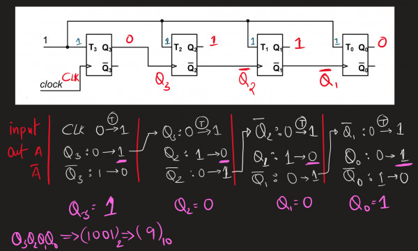
here, input is considered as CLOCK even though actual T – input, which is always set to 1, which means we just have to worry about clock transitions and if it is dependent on some other circuit we have to keep track of it and flip (Toggle) only if both clock raise AND input is 1
for this question, every clock input tends to toggle the bits so we get a complement of the given 4-bit input $(0110)_{2}$ at the outputs as $\overline(0110)_{2} = (1001)_{2}$
(it doesn’t mean we will get complemented output for all cases, it just happened in this case)
hence,
Input to circuit (init) : $Q_{3}Q_{2}Q_{1}Q_{0} = (6)_{10} = (0110)_{2}$
Output to circuit : ${Q_{3}Q_{2}Q_{1}Q_{0}}^{+} = (1001)_{2} = (9)_{10}$
This is the answer to this question (, ie 9 )
you can leave it here, or you can check the next variation :
Variation: SAY $Q_{2}$ is given as input instead of $\overline{Q_{2}}$
Notice the change in diagram $T_{2}$ flip flop‘s output is directly connected to $T_{1}$ flip flop‘s clock
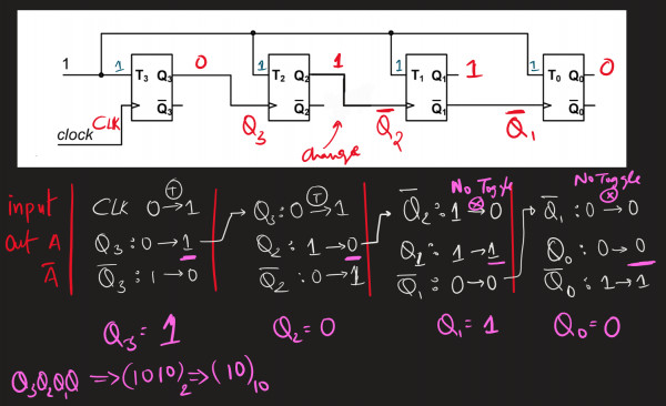
In this case we don't need to flip the bits of $3^{rd}$ and $4^{th}$ Flip Flops.
hence,
Input to circuit (init) : $Q_{3}Q_{2}Q_{1}Q_{0} = (6)_{10} = (0110)_{2}$
Output to circuit : ${Q_{3}Q_{2}Q_{1}Q_{0}}^{+} = (1010)_{2} = (10)_{10}$