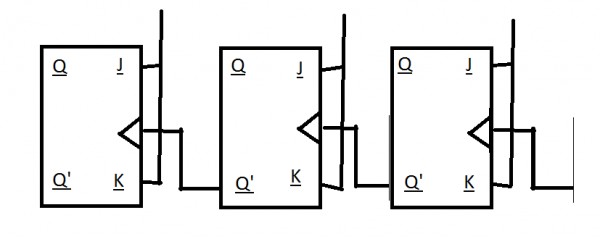
0 votes 0 votes Draw the Wave time diagram for the following counter and what is the mod value of the counter? Assume all J, k are attached to logic 1. Digital Logic digital-logic digital-counter flip-flop + – Shubhanshu asked Apr 29, 2017 • retagged Aug 4, 2017 by Arjun Shubhanshu 849 views answer comment Share Follow See all 0 reply Please log in or register to add a comment.
0 votes 0 votes It is mod8 counter, AnilGoudar answered Apr 29, 2017 AnilGoudar comment Share Follow See all 4 Comments See all 4 4 Comments reply Shubhanshu commented Apr 29, 2017 reply Follow Share thank you.... but what about its movement i.e. it is an up counter or down counter? 0 votes 0 votes AnilGoudar commented Apr 29, 2017 reply Follow Share Down counter as we can see counting sequence as 0 -> 7 -> 6 -> 5 -> 4 -> 3 -> 2 -> 1 -> 0 0 votes 0 votes Shubhanshu commented Apr 30, 2017 reply Follow Share I think it is mod 8 Up counter as in your diagram you have triggered the clock from LHS and in the actual diagram the clock is triggered from the RHS. 0 votes 0 votes Higgs commented Apr 30, 2017 i edited by Higgs Apr 30, 2017 reply Follow Share Yes, It is mod 8 UP Counter. Waveform in the picture is correct but table is incorrect. Q0 is LSB. //In the picture. Remember, in case of ripple counter, flip flop to which external clock is applied, is considered as LSB (irrespective of the whether external clock is applied to the flipflop on the LHS or RHS.) Hence, counter goes through these states: 000 -> 001 -> 010 -> 011 -> 100 -> 101 -> 110 -> 111---- ^ | |___________________________________________________________ 0 votes 0 votes Please log in or register to add a comment.