recategorized by
21,430 views
45 45 votes

For the initial state of $000$, the function performed by the arrangement of the $\text{J-K}$ flip-flops in figure is:

  1. Shift Register
  2. $\text{Mod- 3}$ Counter
  3. $\text{Mod- 6}$ Counter
  4. $\text{Mod- 2}$ Counter
  5. None of the above

10 Answers

Best answer
59 59 votes

Circuit behaves as shift register and $\mod6$ counter

$$\begin{array}{c|c}\hline \textbf{Clock Cycle}  &  \textbf{Output} \\\hline \text{1} & \text{100}\\ \text{2} & \text{110}\\ \text{3} & \text{111}\\ \text{4} & \text{011}\\ \text{5} & \text{001}\\ \text{6} & \text{000}\\\hline \end{array}$$

This is Johnson counter which is an application of Shift Register. And Johnson counter is mod 2N counter.

edited by
28 28 votes

According to me, I think that A, C and D are the answer. Pleas, find the attached screen shot.

24 24 votes
1st approach : Start from 000 and use conventional method (i.e. Truth table) to find modulus.

2nd approach : see, given circuit is nothing but Jonson Counter . Number of States in Jonson counter will be 2n where n is number of flip flops. here n is 3 so number of states are 6 . mod 6 counter..
edited by
10 10 votes

A. Shift Register 
C. Mod-6 Counter


Given circuit diagram is for a Mod-6 Johnson Counter.

edited by
6 6 votes

Ans : A and C 

Shift Register & mod 6 counter. 

3 3 votes

Short method:

Johnson’s counter is Mod 2N counter and ring is Mod N counter.

Detailed  Explanation:

If you look closely at the question, you will notice that the input of J and K are complements of each other and if you recall, if the input values are the complement of each other, JK FF behaves as D FF

Here in the diagram we can see how D FF is formed from JK FF.

So this means the JK in our question will behave as D FF. You can also replace the JK FF with D FF if you want for easier understanding.

So now we can equate the values of J with Q,
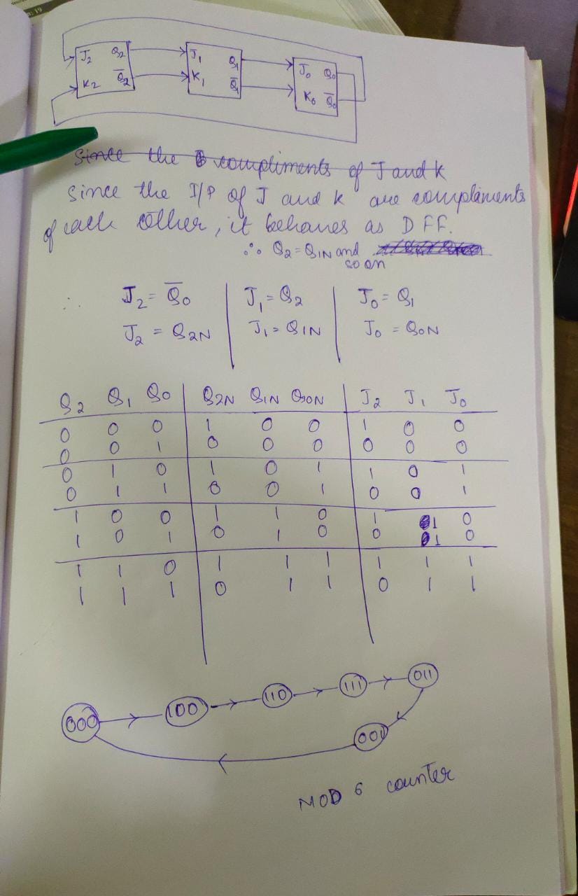
Hence we can get the state diagram. And we will have 6 states since it was mentioned that it will start from 000 thereby eliminating the possibility of MOD 2 counter.

Also the shift register option is correct.

Answer:
Position:
Show:

Related questions

25 25 votes
1 answers 1 answer
5.4k
5.4k views
Kathleen asked Sep 29, 2014
5,412 views
A control algorithm is implemented by the NAND – gate circuitry given in figure below, where $A$ and $B$ are state variable implemented by $D$ flip-flops, and $P$ is cont...
33 33 votes
2 answers 2 answers
11.0k
11.0k views
go_editor asked Sep 20, 2015
10,988 views
If the state machine described in figure should have a stable state, the restriction on the inputs is given by$a.b=1$$a+b=1$$\bar{a} + \bar{b} =0$$\overline{a.b}=1$$\over...
26 26 votes
2 answers 2 answers
12.4k
12.4k views
Kathleen asked Sep 29, 2014
12,415 views
Identify the logic function performed by the circuit shown in figure. exclusive ORexclusive NORNANDNORNone of the above
30 30 votes
4 answers 4 answers
6.5k
6.5k views
Misbah Ghaya asked Nov 15, 2016
6,450 views
The below figure shows four $\text{D}$-type flip-flops connected as a shift register using a $\text{XOR}$ gate. The initial state and three subsequent states for three cl...