In the circuit shown below, $\mathrm{P}$ and $\mathrm{Q}$ are the inputs. The logical function realized by the circuit shown below is
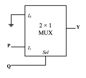
- $\mathrm{Y}=\mathrm{PQ}$
- $\mathrm{Y}=\mathrm{P}+\mathrm{Q}$
- $\mathrm{Y}=\overline{\mathrm{PQ}}$
- $\mathrm{Y}=\overline{\mathrm{P}+\mathrm{Q}}$